


The T60 FrankenPad starts life with several T60 15.0" 4:3 used spares and a shelved spare R61 15.0" 4:3 motherboard – FRU: 42W7822 aka E89382 HannStar J MV-494V-0 [Rockwell – 4 15.0"] which was pulled from R61 model type: 8944-69G – AFAIK these R61 model types were generally available to European customers/markets.
R61 Motherboard FRU
R61 Motherboard top side
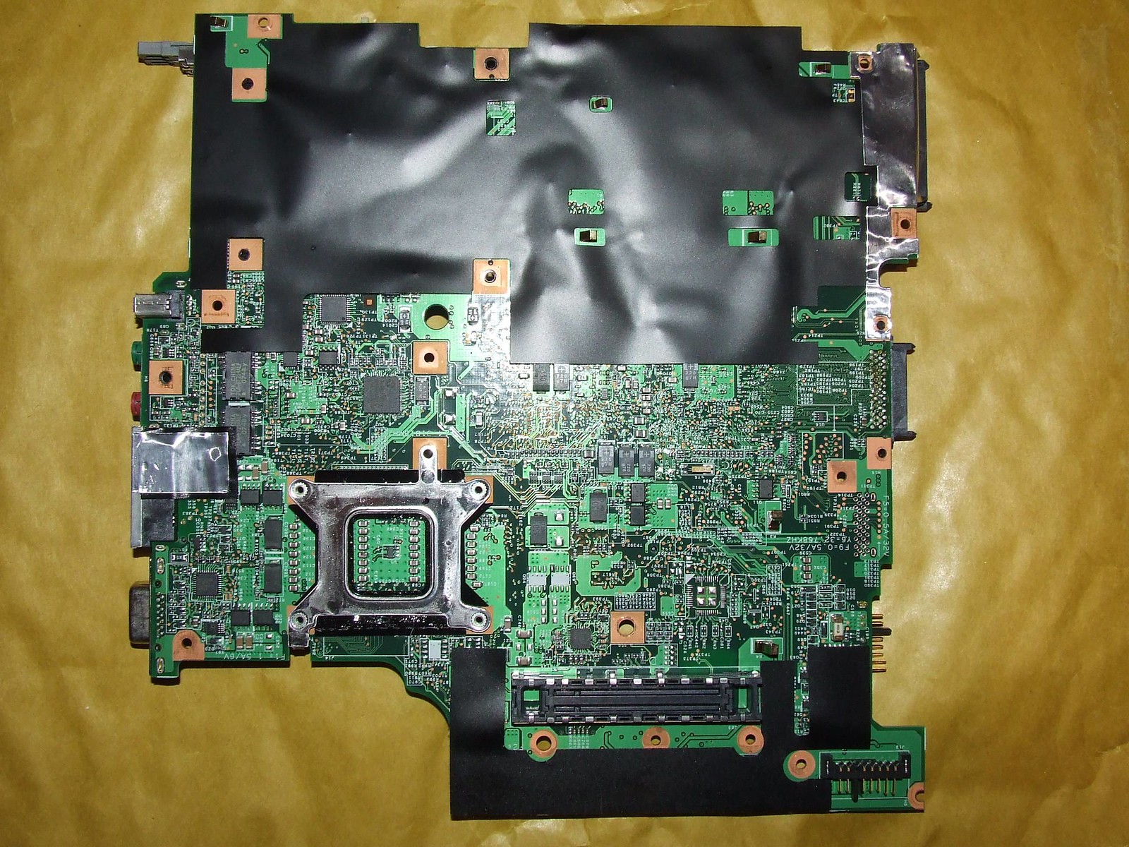
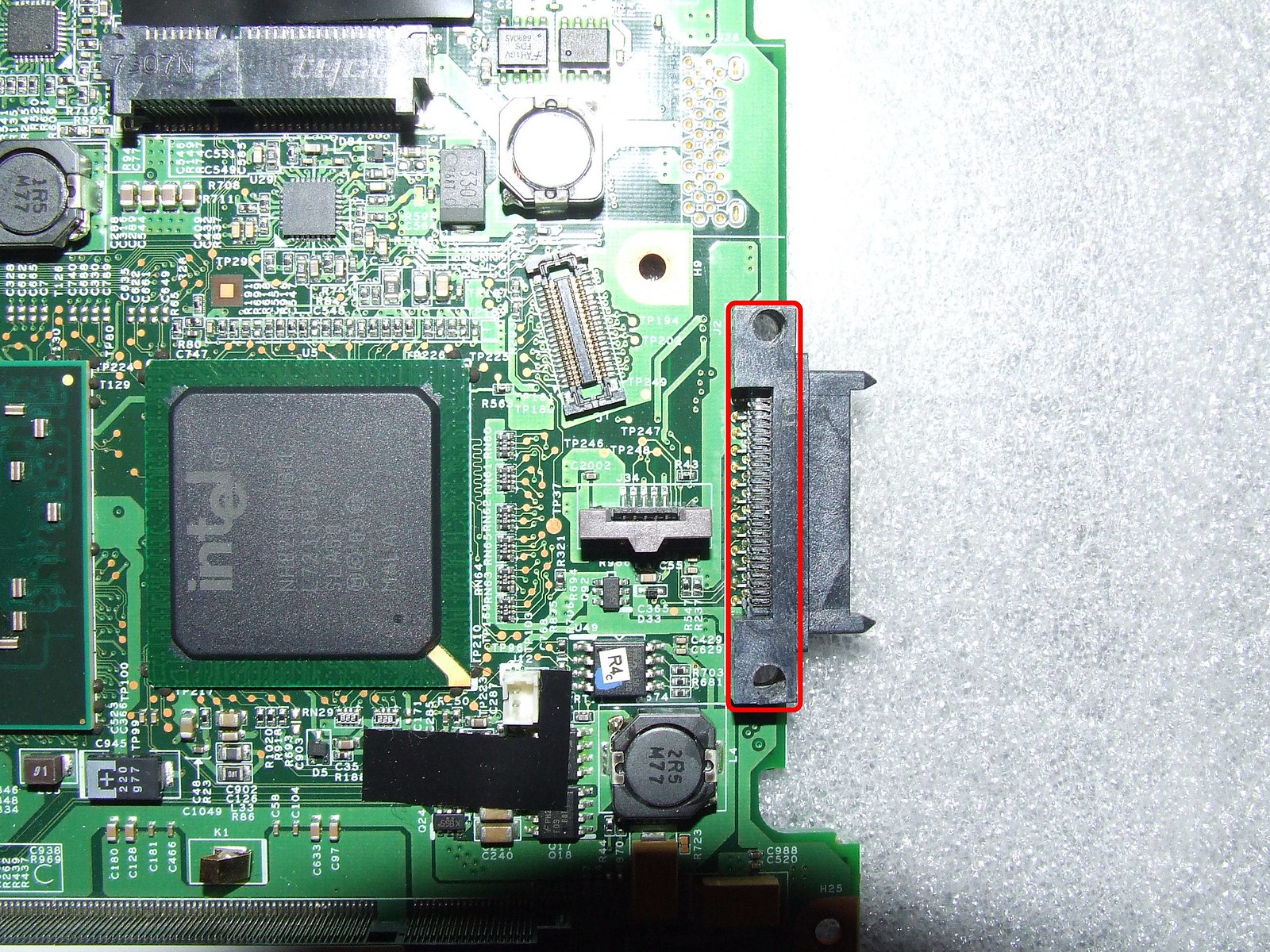
R61 Motherboard bottom side
Placing the R61 motherboard over the bottom of T60's structure frame revealed that most of the motherboard's screw holes (as far as I could see at this stage) seemed to near enough line up with the structure frame's screw holes – but due to an obstructing inductor topside it did not allow a flush fit against the structure frame.
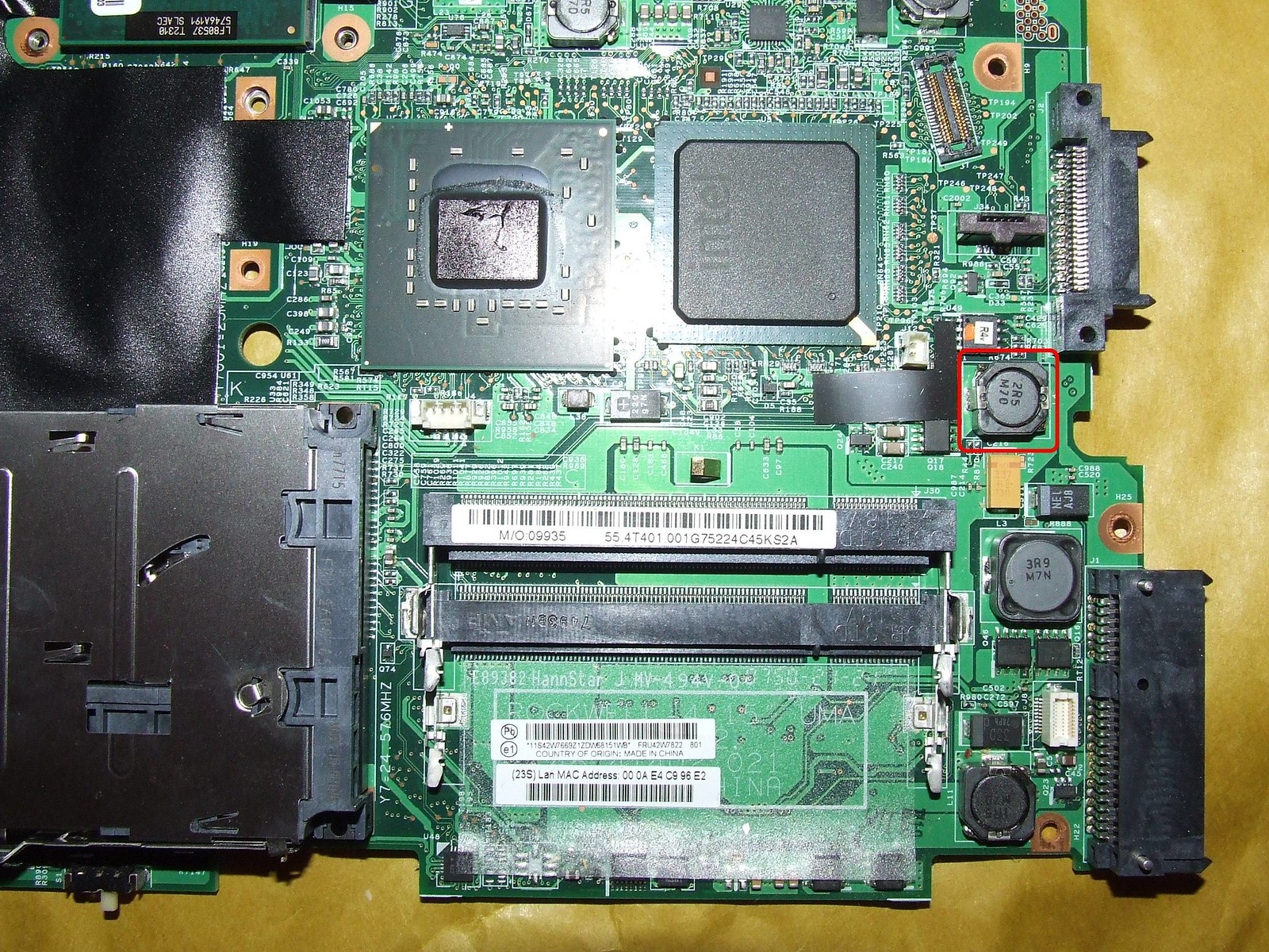
R61 Motherboard – Obstructing Inductor
Also by holding the motherboard lightly against the structure frame and turning it over topside showed that the structure frame would need to be cut to allow the Keyboard, Back up Battery & Palmrest connectors access to the R61's motherboard.
Part-1
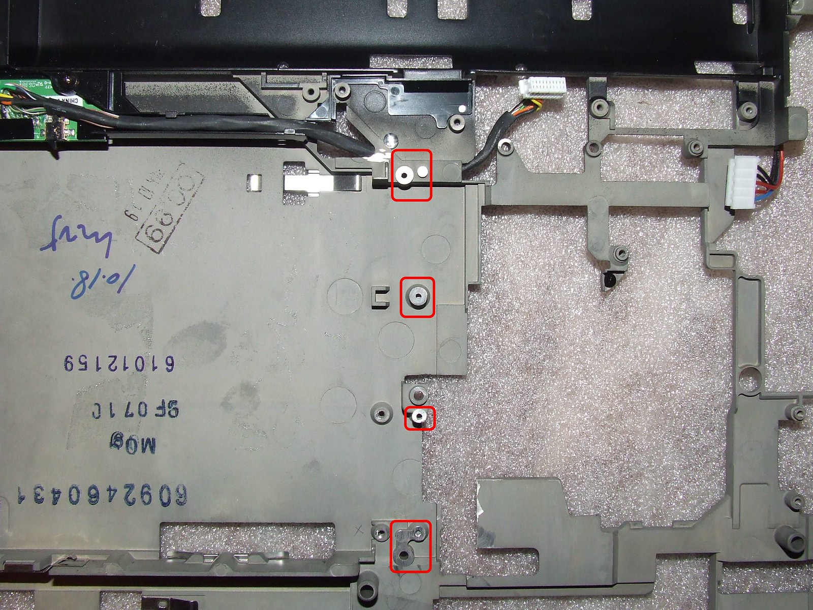
The first modification to the structure frame required the T60's lower interposer screw post to be cut away and grounded down to allow clearance for inductor and also for the motherboard to sit flush against the structure frame.
With the motherboard now resting against the structure frame and viewing the fit from several angles and through the ultrabay, all of the other redundant interposer screw posts and the single top alignment interposer post were ground down to allow clearance from any nearby motherboard surface tracks/pads/connections/components etc.
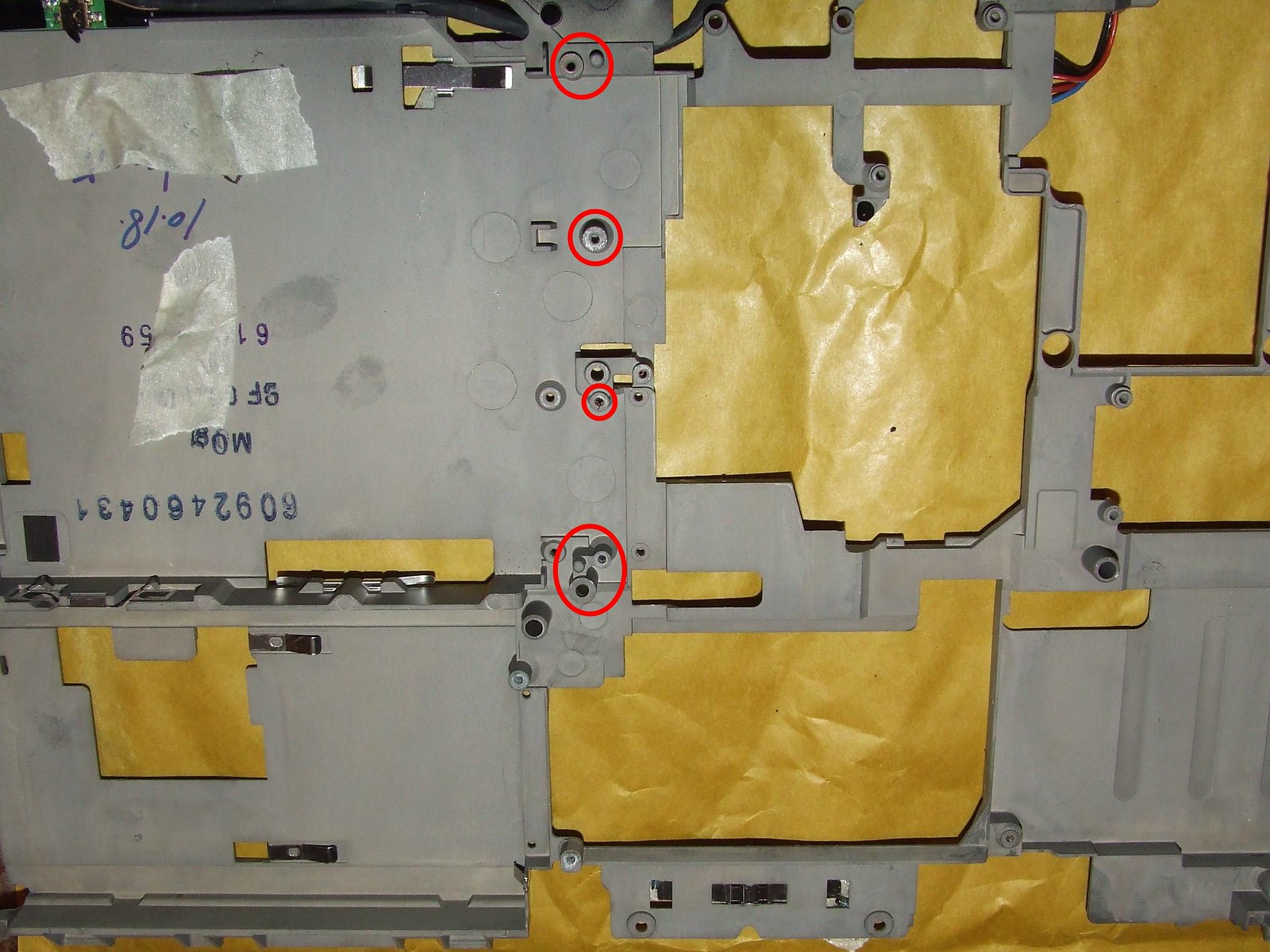
T60 Structure Frame Interposer screw posts
(See also "T60 Structure Frame Cut – View from Bottom – Close Up" picture link below showing the interposer screw posts grounded down)
With R61's motherboard temporary mounted onto the structure frame with a few holding screws, it was found that two screw holes (under where the battery sits) which on a T60 motherboard allows it to be secured to the structure frame was covered by black tape on the R61's motherboard and needed to be opened/punched through – this was achieved with a 3mm drill bit
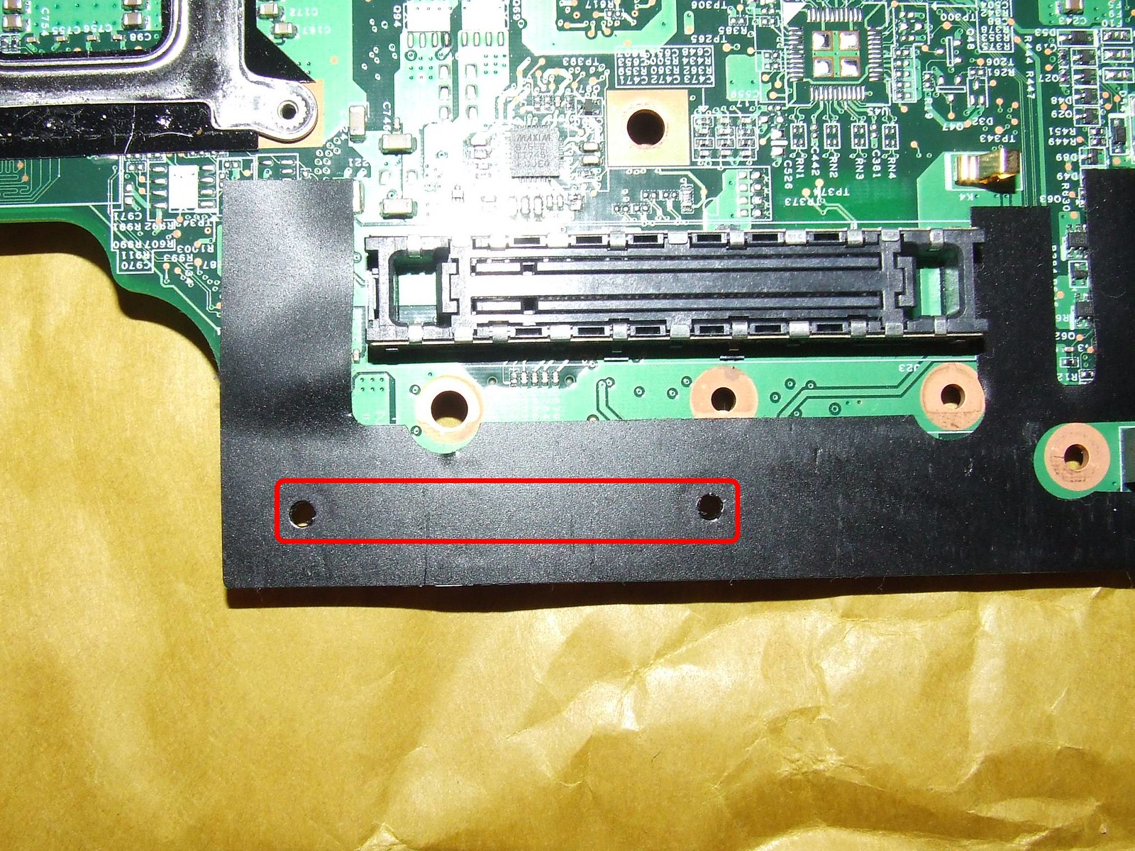
R61 Motherboard – Black Tape Unpunched
R61 Motherboard – Black Tape Punched
Also two screws which goes through from the motherboard to DVD/CDRW connector block to the structure frame did not fully align with the structure frame.
Thinking it through one way to allow near/closer alignment is to widen the existing motherboard screw hole pads and DVD/CDRW connector block holes, this could prove fatal as there could be the possibility of cutting through hidden internal tracks if present and also any unwanted excess pressure to the DVD/CDRW connector block mounting could somehow damage it too!
Taking a risk it was decided to SLOWLY and VERY CAREFULLY drill through the two motherboard screw hole pads approx 1.5mm in depth, then drill from the top of the DVD/CDRW connector block mounting holes down through to the motherboard using a hand drill, first with a 2.5mm drill bit and then a 3mm drill bit – Although a little tight, the screws were able to be secured into the structure frame.
R61 Motherboard – DVD/CDRW Connector Block widened/drilled
R61 Motherboard – Screw Hole Pads widened/drilled
Part-2
The next job was to cut away the unwanted metal from structure frame to allow the Keyboard and Back up Battery connectors (which were completely covered) & Palmrest connector access to the R61's motherboard – This was done carefully with a Dremel which took close to an hour as I am not a Dremel expert and yes this was my first time using one –
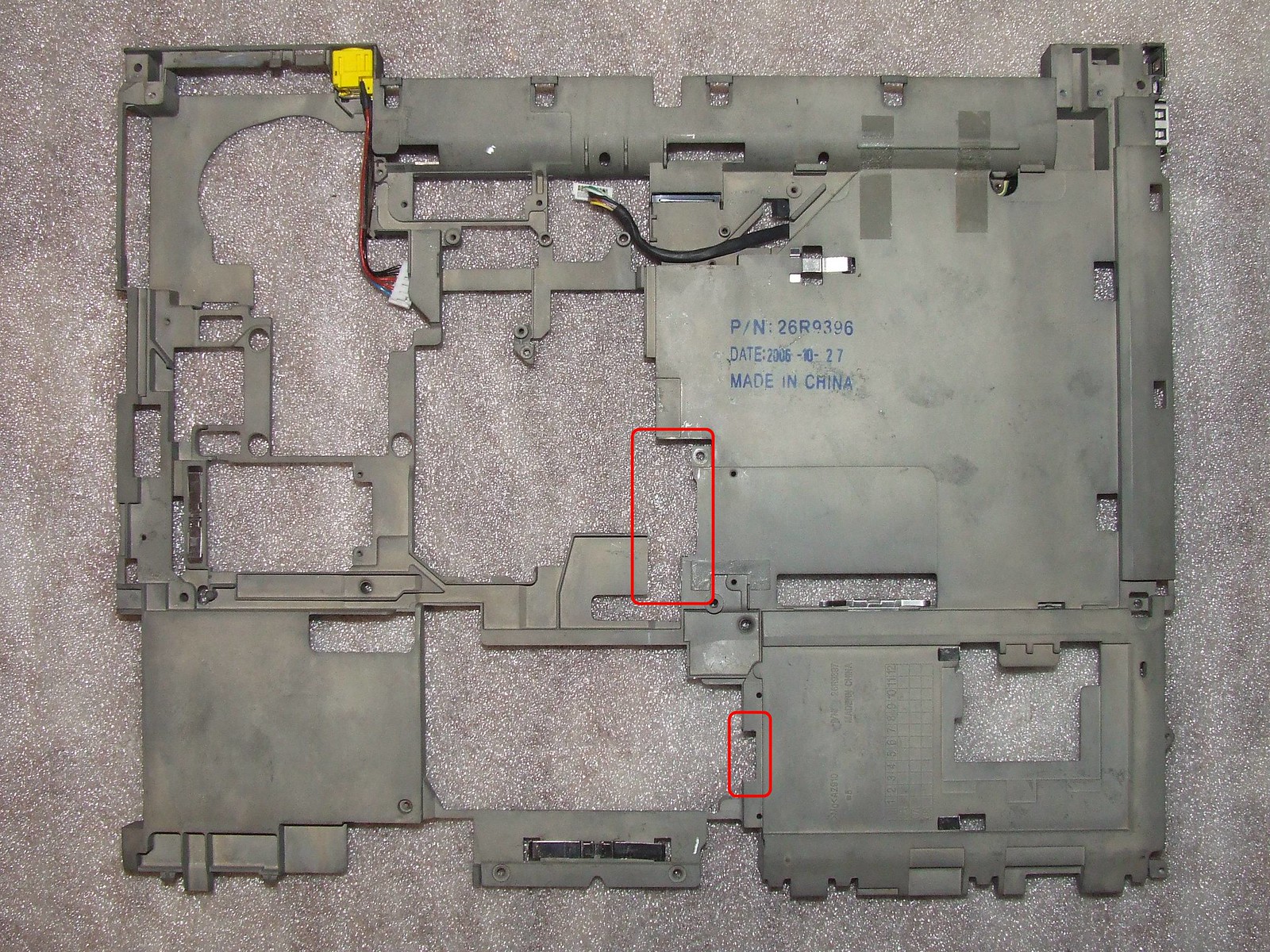
T60 Structure Frame Cut – View from Top
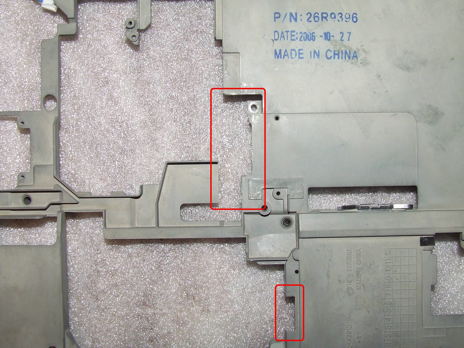
T60 Structure Frame Cut – View from Top - Close Up
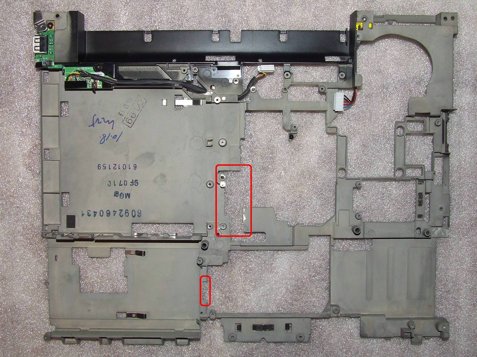
T60 Structure Frame Cut – View from Bottom
T60 Structure Frame Cut – View from Bottom – Close Up
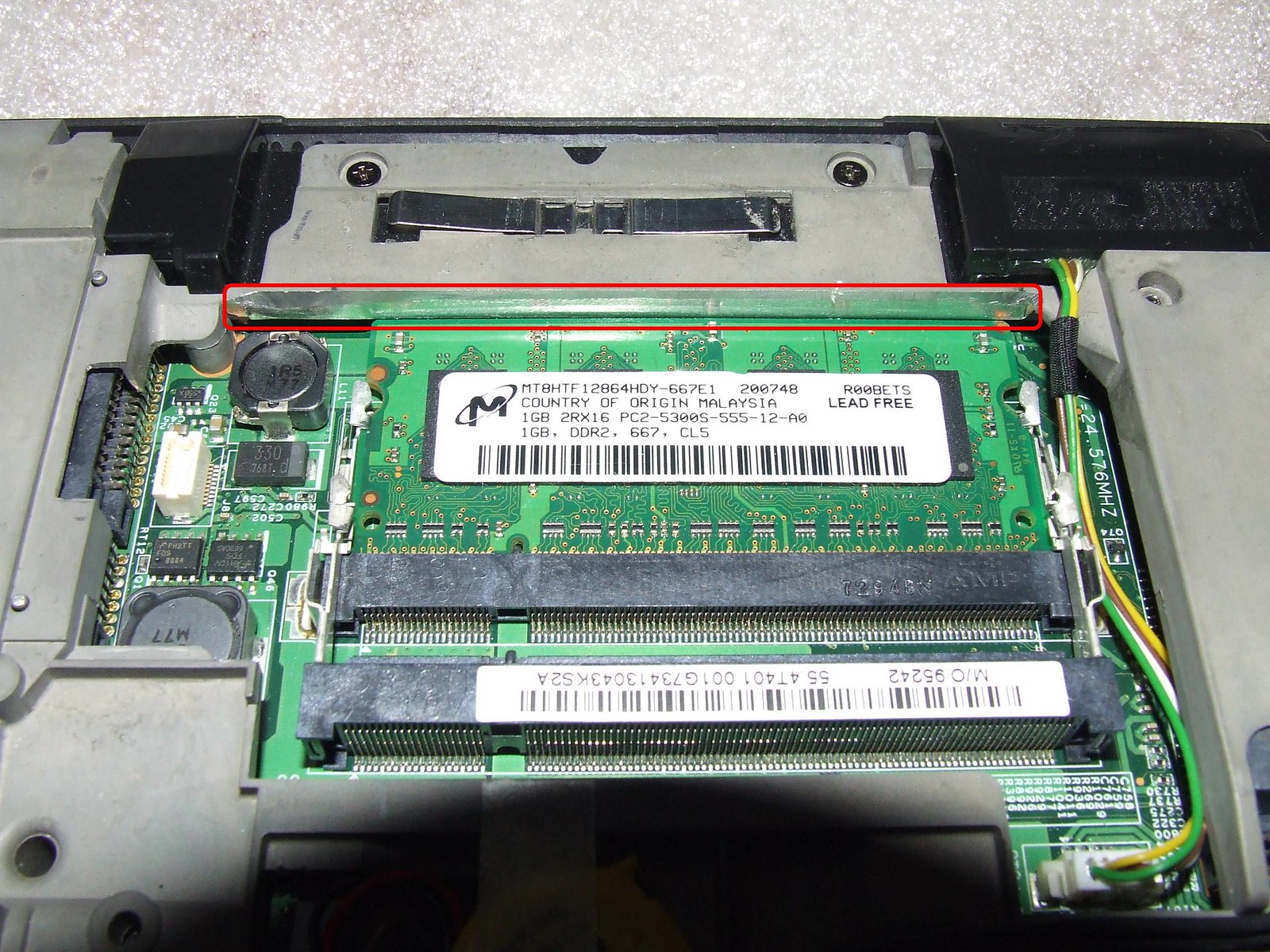
Now with the R61's motherboard re-screwed down to the structure frame, it was found that when a stick of RAM was placed into the lower RAM slot, it was unable to reach the retaining clips – this was made good by very carefully hand filing along the lower inside of structure frame – Note: this part of the structure although seems solid is thin, hence care was taken to not apply heavy excessive file strokes!
T60 Structure Frame lower inside filing to allow fitment of lower stick of RAM
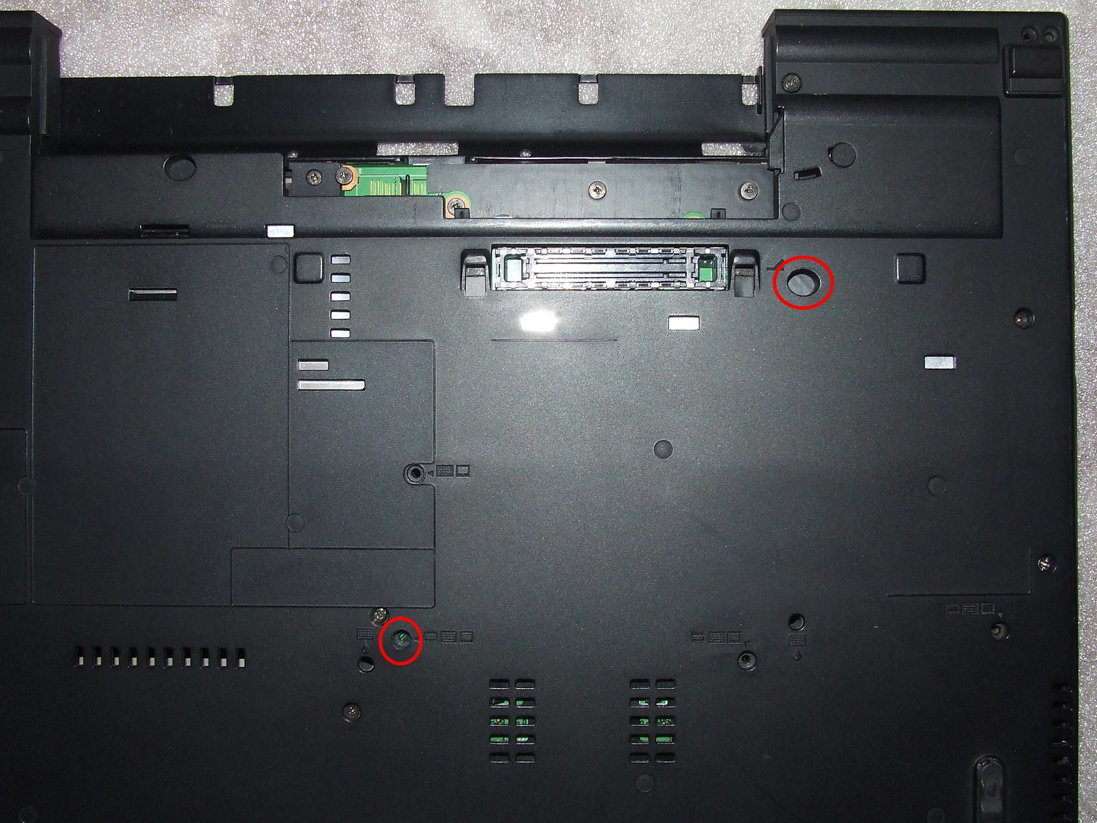
Finally with the R61 motherboard competely and fully screwed down to structure frame, the whole assembly was now lowered into the T60's base cover to check screw alignment with the structure frame – Once again the only screw that did not align was one that needed to pass from the base cover through the motherboard to DVD/CDRW connector block to the structure frame (which was already widened as per above) – this was fixed by carefully drilling the base cover screw hole with a 3mm drill bit which still retained much of the internal shoulder of the screw hole to allow the screw to be tightened against.
One of the palm rest base cover screw holes was blocked due to motherboard covering it – therefore making only three screws available to the palm rest from the base cover
The motherboard was also visable through one of the base cover docking station holes - a piece black insulation tape was placed onto the motherboard as a precaution just in case the dock station pin should short or damage any of the motherboard's pads/tracks/connections when attached.
T60 Base Cover
T60 Base Cover – Blocked Palm Rest screw hole & Docking Station hole with insulation tape already applied to motherboard
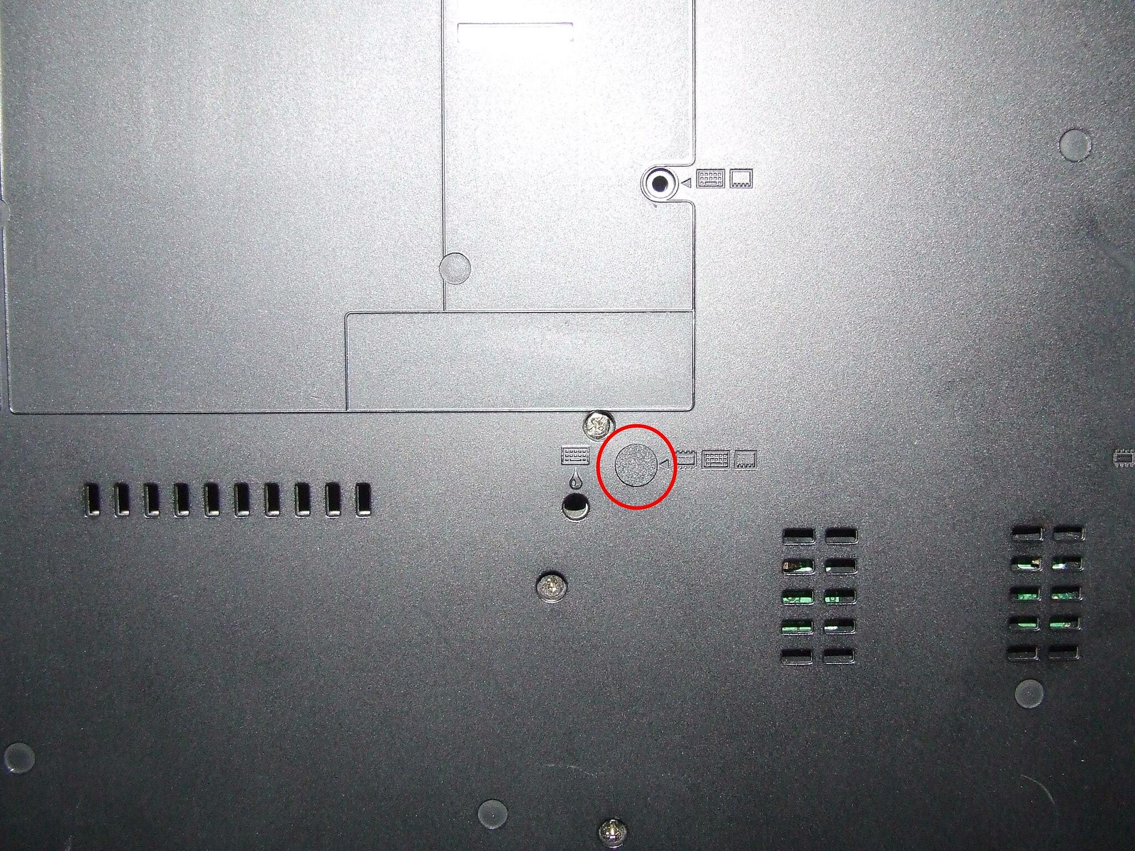
T60 Base Cover – Blocked Palm Rest screw hole covered with an LCD adhesive screw cap
R61 Motherboard – insulation taped applied and shaped to motherboard contour
Part-3
With the R61 motherboard attached to structure frame and mounted within the T60's base cover, the following components were installed to complete the FrankenPad:
T7300 CPU & T60 heatsink assembly
2 x 2GB sticks of RAM & Back up battery
Modem & WiFi module
LCD assembly with UXGA BOE-hydis IPS/FlexView panel
Keyboard, Palmrest, HDD assembly, DVD/CDRW drive & Main Battery
>>> T60 FrankenPad completed <<<
The FrankenPad fired up ok with no prob's -
Additional info:
At all times during alignment and fitting of the motherboard with the structure frame, extreme care was taken to thoroughly brush off and blow away any excess metal filings/swarf so as to prevent any shorts - ESD precautions were also taken.
The Palm rest seems to be secured ok with just three screws
The following ports are not compatible with the T60's chassis and therefore redundant from the R61's motherboard: S-Video & Mini FireWire assembly.
No IR port is available as per the T60 motherboard's as the R61 motherboards does not support one.
Middleton's BIOS has been applied so as to allow non-whitelisted WiFi cards and enable SATA II 3.0Gb/s throughput for a future SSD upgrade – No plans for a Penryn upgrade (if supported) for now .
This FrankenPad runs flawlessly and is quiet too! - Recommended -
Apologies if this post is a little long winded, but it is hoped that it gives an alternative insight to creating a T60 FrankenPad with an IPS/FlexView panel and spare R61/R61i 15.0" 4:3 Intel GM965 motherboard.
Of course an easier method is just to find a R61/R61i 4:3 15.0" (Model types: 8942 – 8949) and just replace the existing LCD panel with a 15.0" IPS/FlexView


