wileE wrote:
No problems yet on battery (will check with empty batterys tomorrow). Brightness on battery is the same as on AC. 256 nits max.
Good to know, especially your empty-battery update.
But I have a big problem with the brightness steps.
http://imgur.com/ycYNTfn That is only 3 steps I am likely to ever use. And step 13 only very rarely.
Anything I could do to get a few more steps in the useable range?
Thanks for the scale, that will help. Yes, there's something to do, you'll need to replace a resistor with a different value. Let me try it here today on one of my scratch boards to get the right ballpark. You said you're unlikely to ever want less than 60 nits under any circumstances, right?
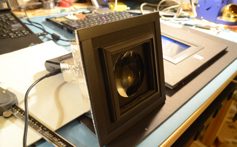
Positioning the strip in the bracket is also proving to be difficult. Pressed against the waveguide, as I did with all the X6x screens, results in distorted mirror images of the LEDs in the lower 1.5 cm of the screen.
With the strip on the bottom of the bracket it is much better. Tried double sided ahesive tape and pressing it down with the help of platic strips. But it does not stay there when the LEDs get warm. I am reluctant to use glue.
Hm, this screen must use a very weak diffuser to increase brightness, or has no bottom diffuser. The 'best' way to fix that problem is to slip a stronger diffuser layer between the waveguide and prism layer, but it requires popping the screen frame open. Good diffuser sheets should be ~ readily available but I don't know the internal dimensions to cut for WSXGA. I could tell you for the X60/61 screens.
You could also get some inexpensive sheets of clear PET plastic, slice thin strips on a paper cutter, and use them as spacers in front of the LED strip. Farther away will probably reduce brightness more than using a stronger diffuser.
(It is hard for me to tell what a normal diffuser setup in each screen is because I've bought lots of reclaimed screens and it appears each and every unit has been tampered with-- none have what appear to be stock diffuser layers in them. On the other hand, I have played quite a bit with the screen internals.)
But I cannot recommend the LED strips from creatall88. In the LG WSXGA+ the resulting yellow-green tinge is ugly.
Yes, that was my experience too, along with brightness variations between the LEDs on the same strip.
I have built my strips and commenced more careful measurement using my spectrometer rather than simply trying to use my DSLR and making educated guesses

The binning process was a success-- my strips have nice even color and brightness. Unfortunately, the final specs are not as perfect as hoped. The color balance is good, but a bit warm (~6000k instead of 6500k) and the brightness is slightly below that one perfect strip I got as a sample using the same manufacturer's LEDs. I am being very picky of course-- they're fully twice as bright at the same power as CCFL. But I wanted so badly to recreate that one perfect sample that came out of nowhere and I've never found again. It's the best backlight strip I've ever measured.
I'm also retesting strips I got from other suppliers. The Simpleboost LEDs are better than I remembered-- not quite as bright as my strips, but nearly perfect whitepoint. I have an iCCFL strip that is slightly greenish, but hits nearly 300% the original CCFL brightness without seeming too far off on color. I'll have some actual numbers in a bit.


