Nice findings, RMSMajestic!
With your hint regarding the voltage, I was finally able to unlock my QX9300 as well. This is how it always works for me:
1) Start CPU-Z.
2) Start Throttlestop 6.00.
3) Choose an unused profile (for me e. g. number 2 "game").
4) Choose multiplier 9.5 and voltage 1.2625 and set the "Set multiplier"-hook.
5) Click "UNLK".
6) Click "Turn On". CPU-Z will show the default voltage (1.175V) despite this.
7) Click the "arrow-up"-button next to the voltage value 1.2625. The value in Throttlestop will not change, but CPU-Z will now show 1.188V.
8) Click the "arrow-down"-button next to the voltage value until it is 1.175. CPU-Z will now show 1.175V
9) Click the "arrow-up"-button next to the multiplier value to set it to 10.0. This had no effect before but if you run a stress test like prime95 now, you will see that the setting has been applied this time and the QX9300 will run at 2.666 MHz. Now you can choose all multipliers and voltages and they will be applied and shown in CPU-Z accordingly.
I had it running at 3.066 MHz (11.5 and 1.175V) but even at fan level 64 the temperature got over 95°C with prime95 in-place large FFTs and the system became unstable. If the cooling would be better, I think these settings would work well. With higher voltages (e. g. 1.250 V), the system seems to crash much earlier (although the temperature has not reached 90°C yet), so I think that keeping the voltage and power consumption down will give better results than trying to crank up the voltage to achieve higher speeds.
But to be honest, the default clock is sufficient for me. I had the CPU running at 1.050 V on all multipliers from 6 to 9.5 for the last three weeks and it was stable. I will most likely leave it like that.
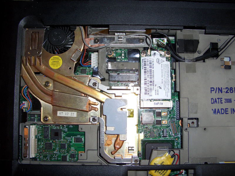
With your hybrid-watercooling and fan level 64 you might be able to run 3.066 GHz stable. For me, mobility is a key feature, so it has to be stable on air cooling. This week, I got a T61-4:3-nvidia-cooler and was able to swap its fan against the one from the T500-ATI-cooler (as announced
here and already done
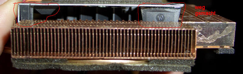
here). I removed the two black plastic parts next to the fan since I had the impression that they rather block airflow than guide it.
http://abload.de/img/cimg2189sek03.jpg (47,06 KB image link)
Also, I drilled six holes into the base cover so that the fan gets more fresh air from the outside.
http://abload.de/img/cimg2180zvjjq.jpg (93,94 KB image link)
http://abload.de/img/cimg2184xek79.jpg (88,41 KB image link)
To mount the fan assembly, I sawed out the lower right mounting point for the T61 cooler mounting bracket of a T61 14,1" 4:3 structure frame and glued it to the T60 15" 4:3 structure frame, so that I did not have to modify the fan at the metal bloc in the middle but could use the T61 cooler mounting brackets instead .
http://abload.de/img/cimg2166dukxk.jpg (121,37 KB image link)
At 2.533 GHz (multiplier 9.5 and 1.050 V) and fan level 64, the maximum temperature with prime95 in-place large FFTs is around 78°C.
http://abload.de/img/temps7kyd.jpg (screenshot, 794,21 KB image link, those with slow connections, beware !)
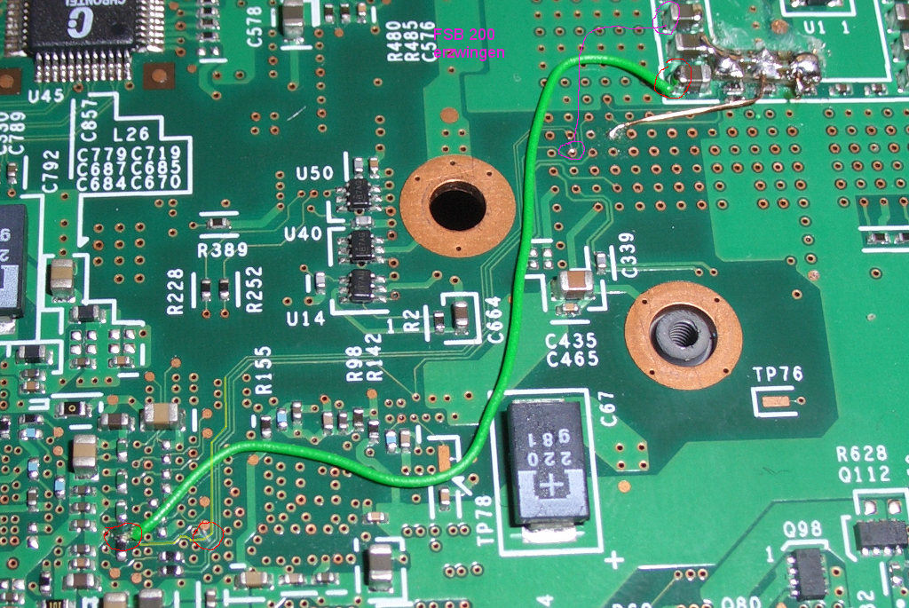
RMSMajestic wrote:So, I guess we can conclude that T61 does have some limit in total power consumption. And this is confirmed by amwrdfe, who found the following part on T61 circuit diagram
I had a look at this. I do not think that the overall current limit, which is set at MAX8765, is the only problem. The CPU current limit, which is set at ADP3207, might also play a role.
Refer to the second equation on the right on PDF page 18 in the MAX8765 datasheet. If I did not make a mistake, the overall input current limit should be around 133 W (which would make sense, since the most powerful AC adapter has 135 W) because RS1 is 0.01 Ohm (R380 in the T61 schematic) , V_ref is 4.096 V, V_cls should be 3.624 V regarding the resistive divider with R157 and R904 in T61 schematic on PDF page 76.
The CPU limit should be (again, if I did not make a mistake) around 49 A, but I am not 100% sure here because I do not know if the 13 mV/µA from the design example in the ADP3207 datasheet is always the right value for A_lim. Refer to equation 25 on PDF page 24 of the ADP3207 datasheet. R_o is 2.1 mOhm in their design example and according to figure 4 in the intel mobile C2Q datasheet, the loadline slope is -2,1mV/A, so that 2.1 mOhm from the design example should be ok. R_lim is 215 kOhm according to the T61 schematic (R246 on PDF page 82) and if we assume that we can take the 13mV/µA from their design example (I do not know if this assumption is good), then the current limit for the CPU would be 49A.
According to the intel C2Q datasheet, the ICC design target is 64 A for these CPUs. For the Socket P merom C2D CPUs, the ICC design target was 44 A. I am sure that the CPU current limit is the reason for your shutdowns at default voltage with intel CPU burn test (assuming that the cooling was sufficient while running the test) because the "CURRENT-LIMIT, SHORT-CIRCUIT, AND LATCH-OFF PROTECTION" seems to be able to cause such restarts if the CPU current limit is exceeded over some period of time.
ADP3207 datasheet wrote:After a current limit is hit, or following a PWRGD failure, the
SS pin is discharged by an internal sink current of 2 μA. A
comparator monitors the SS pin voltage and shuts off the
controller when the voltage drops below about 1.65 V. Because
voltage ramp (2.9 V − 1.65 V = 1.25 V) and discharge current
(2 μA) are internally fixed, current-limit latch-off delay time
can be set by selecting the external SS pin capacitor.
On W700, R_lim is 121k which would give a current limit of 87 A if the other values would be the same. This seems a bit high to me and it is very likely that the value for A_lim is a bit lower for W700, since W700 has a three phase design and according to the datasheet, the number of phases play a role here, but I did not fully understand what the impact is on the equation.
Lets assume that A_lim is a bit lower, e. g. 10 mV/µA, then we would get a current limit of 67 A, which seems more reasonable to me.
Conclusion: R_lim (R246 in T61 schematic) should have a lower value to have a higher current limit for the CPU if one wants to overclock it. Another possibilty would be to entirely disable the current-limit latch-off function:
ADP3207 datasheet wrote: To
disable the current-limit latch-off function, an external pull-up
resistor can be tied from the SS pin to the VCC rail. The pull-up
current has to override the 2 μA sink current of the SS pin to
prevent the SS capacitor from discharging down to the 1.65 V
latch-off threshold.
Otherwise, the best thing to do is undervolt the CPU to 1.050V (or the lowest possible value where the CPU is stable) for all multipliers with throttlestop to lower power consuption and heat.


